
The H key will display handles that can be used to change the offsets for side objects. Changing the Start / End Offsets can be done in the Inspector or in scene view. It is recommended to do this in Build Mode with the terrain already adjusted.

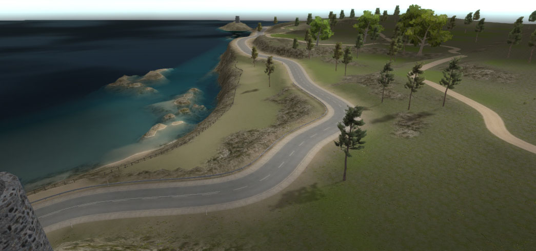
This can be fixed by tweaking the Start / End offsets for this wall side object on th respective markers. Due to the grid nature of the terrain it is very likely that there will be a small gap between the wall and the terrain at the start and end. What needs special attention is whether the wall aligns nicely with the terrain at the start and end. The reason why this setting is automatically updated is because we marked this side object as a Terrain Surface Object in the Side Object Manager. As mentioned at the start of the tutorial, this will make sure that the terrain is not leveled with the road on that side. "Left Indent Alignment" is auto set to "Align with the terrain" instead of the default "Align with the road". In the main image above the side object is for example activated for the markers 8 up to 12 on the left side of the road. Using this side object in the scene is fairly simple. The guard rail in the above screenshot is an additional side object, "Guard Rail Rock", positioned on top of the wall. If you would set this to "None" or "Path Forward" the side object will break through the road. The wall will align exactly according the road normal. Alpha 1 for the wall texture, alpha 0 for the dirt ground texture between the wall and the road.īecause the side object extends underneath the road and we are using a little bit of tilting on the road shape "Terrain Alignment" is set to "Path Normal". And the vertex colors assigned to node 2 and 3, alpha 0. The shadows on the road will now look the same as projected on the wall.Īlso note the vertex colors assigned to node 1 and 2, alpha 1.

Therefore we simply extend the wall side object to cover this area. Since the terrain is no longer flattened exactly underneath the road, the shadows on the road will look wrong. The shadows projected on the road will actually be the shadows projected on the object below the road. The reason why the wall side object extends all the way to the right is because the mountain road uses the decal:blend shader, explained here. Nodes 2 and 3 cover the area below the road and have negative y values to make sure the road is rendered on top. The wall shape is defined in the Shape Editor Window, "Open Shape Editor Window" button. This side object generates a wall based on the Shape side object type. This will auto adjust terrain alignment settings for the affected markers which is covered further below. The first thing to do is mark this side object as a Terrain Surface Object.


 0 kommentar(er)
